5600 Replacing the DME Management Module
Contents
[[#Preliminary Activity Tasks]]
[[#Replacing the Management Module in the Data Mover Enclosure (DME)]]
[[#Check the system for Faulted Hardware]]
[[#Continue troubleshooting the Management Module switches]]
[[#Prepare the system for maintenance (Callhome does not need to be disabled)]]
[[#Remove failed Management Module]]
[[#Install the replacement Management Module]]
[[#Configure the system with the replacement Management Module/switch]]
[[#Restore NAS Services and CS1]]
[[#Perform system Health Check]]
Preliminary Activity Tasks
This section may contain tasks that you must complete before performing this procedure.
Read, understand, and perform these tasks
- Table 1 lists tasks, cautions, warnings, notes, and/or knowledgebase (KB) solutions that you need to
be aware of before performing this activity. Read, understand, and when necessary perform any
tasks contained in this table and any tasks contained in any associated knowledgebase solution.
Table 1 **List of cautions, warnings, notes, and/or KB solutions related to this activity
489302: If you are using Data At Rest Encryption (D@RE) on your VNX2 array, perform a Keystore
Backup prior to the NDU and store the backup image on a host system: Unisphere > System >
System Management > Backup Keystore file
488877: In Rel 33 P155 during a controlled reboot, an issue maybe encountered where a lun(or luns)
may not accept I/O for 50+ seconds during the trespass process. There is a strong probability that
this issue will be impactful when upgrading from Rel 33 P155 to any later release of code. Dell EMC
strongly recommend to installs KB488877-01.01.5.001-armada64_free.ndu (available on
support.emc.com) prior to attempting an install of any VNX OE version when upgrading from Rel 33
P155.
301857: Do not perform a VNX OE NDU on any VNX Storage Processors connected to a VPLEX
running any VPLEX GeoSynchrony version. Do not perform a proactive Storage Processor reboot on
any VNX Storage Processors connected to a VPLEX running any VPLEX GeoSynchrony version.
Refer to
ETA 182792 https://support.emc.com/kb/182792,
ETA 193541 https://support.emc.com/kb/193541, and
ETA 197315 https://support.emc.com/kb/197315.
Note: There may not be any top trending service topics for this product at any given time.
VNX Top Service Topics
Replacing the Management Module in the Data Mover Enclosure (DME)
Note: This procedure is non-disruptive to File server services.
Check the system for Faulted Hardware
There are several ways to diagnose and identify the faulted component:
• Unisphere:
You can log in to Unisphere to diagnose a problem with a hardware component. Do the following:
1. Open an Internet browser and enter the following URL:
https://
where is the hostname or IP address of the primary Control Station (CS0).
2. Login as sysadmin and set the scope to Global (Login as root user scope Local for a Gateway
system).
After logging in, the Unisphere Dashboard page appears. Unisphere displays the system’s
hardware component status and the alerts for managed systems on the Dashboard. You can right-
click on any new alert in the Alerts quadrant and select Details to view the associated error
message.
3. Use the drop-down list at the top left of the Dashboard to select the system that contains faulted
hardware.
4. Select System > Hardware > Hardware for File to view information about the components.
5. Check the system inventory for faulted hardware components.
6. Record the full component name for any faulted hardware found on the Hardware for File page.
The component name contains important information about hardware location.
• Physically check for faulted components:
1. From the rear of the cabinet, locate the management modules in the system (Figure 1) for each
Data Mover Enclosure.
Dell Technologies Confidential Information version: 7.0.6.69
Page 4 of 9

Figure 1 Example: Management Module DME0 B-side
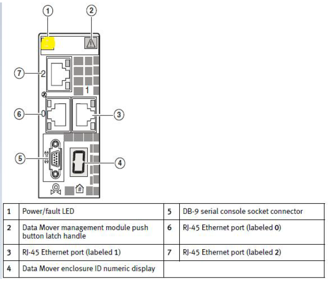
2. Check for a Power/Fault LED for each Management Module (Figure 2).
• If the Power/Fault LED is solid amber, the management module is faulted and must be replaced.
• If the Power/Fault LED is green, the management module is functioning normally.
Dell Technologies Confidential Information version: 7.0.6.69
Page 5 of 9
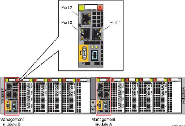
Figure 2 Management Module on DME 0 with Fault LED
3. If the management module LEDs or Unisphere indicate a faulted management module, skip the
next Task. If, however, there is no fault LED, but the Management Module is suspected of
malfunctioning, continue with troubleshooting in the next Task.
Continue troubleshooting the Management Module switches
1. [ ] Ping the hostnames of the management modules in each suspected Data Mover Enclosure
(Table 1). The following example shows a four enclosure system.
ping
Mgmt Module Hostnames and IP Addresses
| Enclosure ID | Module A Hostname | Module B Hostname |
|---|---|---|
| 0 | mgmt_2_3 128.221.252.50 | mgmt_2_3b 128.221.253.50 |
| 1 | mgmt_4_5 128.221.252.51 | mgmt_4_5b 128.221.253.51 |
| 2 | mgmt_6_7 128.221.252.52 | mgmt_6_7b 128.221.253.52 |
| 3 | mgmt_8_9 128.221.252.53 | mgmt_8_9b 128.221.253.53 |
2. [ ] If a particular Module fails to ping, continue with the next Task to replace the component.
Prepare the system for maintenance (Callhome does not need to be disabled)
1. [ ] From the serial console session on the primary Control Station (CS0), power-off the Standby
Secondary Control Station (CS1), as required, and verify:
# /nas/sbin/t2reset pwroff –s 1
# /nas/sbin/getreason
10 - slot_0 primary control station
- slot_1 powered off
2. [ ] Stop NAS services on CS0:
IMPORTANT: Stopping NAS services will unmount the /nas partitions. In a later step the partitions
will be manually remounted in order to perform certain commands. Do not to attempt to run this
command while working in the /nas directory.
# /sbin/service nas stop
This command can take several minutes to complete. If this command fails, reboot CS0, wait 15
minutes, then try again.
3. [ ] Manually mount the /nas partitions and continue with the next Task:
# mount /nas
# mount /nbsnas
# mount /nas/dos
Remove failed Management Module
- Verify/label the Management Module cablea, then remove the cables from the faulted module.
- On the faulted Management module, depress the orange button and pull the trigger mechanism
on the module handle to release the module from the blade enclosure (Figure 3). The Management
Modules are in the first slot position on the A and B side of the enclosure. The example below shows
Management Module B.
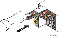
Figure 3 Removing/Installing Management Module B
Install the replacement Management Module
1. [ ] Align the replacement module with the guide on the sides of the blade enclosure (Figure 3) and
insert while pushing on the orange button, then releasing the button when fully inserted..
--If the button remains in, the module is fully seated.
--If the button springs back, push the button again while seating the module further into the chassis. If
the button does not rest flush with its handle, remove the module and repeat the installation process.
2. [ ] Re-attach the cables per the labeling.
Configure the system with the replacement Management Module/switch
1. [ ] Execute the following command to replace the old switch with the new Management Module
switch:
/nas/sbin/setup_enclosure -replaceMgmtswitch
Example:
# /nas/sbin/setup_enclosure –replaceMgmtswitch 0
where is the Enclosure ID containing the replacement management
module. Table 2 lists the blades associated with each enclosure.
Table 2 Enclosure ID and Blade Association
Enclosure ID Blades
0 2 and 3
1 4 and 5
2 6 and 7
3 8 and 9
2. [ ] If either of the following errors appear when running the setup_enclosure command, correct as
follows:
--TFTP service is enabled by T2PXE. Stop TFTP service with ’t2pxe –tftp stop’
Error: REPLACEMENT_CMD retval \= -46 (ETFTP)
--Error: T2PXE is using DHCPD. Stop T2PXE services with ’t2pxe -e’
Error: REPLACESWITCH_CMD retval \= -49 (EDHCPDBUSY)
a. Correct the error by disabling the TFTP service, or PXE service, respectively, as indicated in the
error message:
/nas/sbin/t2pxe -tftp stop
/nas/sbin/t2pxe -e
b. Then, retry the setup enclosure command:
/nas/sbin/setup_enclosure -replaceMgmtswitch
3. [ ] Verify that the Fault LED on the management module has cleared (this may take a few minutes).
a. Use the following commands for additional management module (switch) troubleshooting:
/nas/sbin/setup_enclosure -checkCable
/nas/sbin/setup_enclosure –checkSystem
Restore NAS Services and CS1
1. [ ] Restart NAS Services and wait approximately 15 minutes for all services to restart:
# /sbin/service nas start
# /nas/sbin/getreason
10 - slot_0 primary control station
- slot_1 powered off
5 - slot_2 contacted
5 - slot_3 contacted
2. [ ] Restart the Standby Control Station (CS1), if applicable, and wait for it to reboot:
# /nas/sbin/t2reset pwron –s 1
Perform system Health Check
Check system status:
/nas/bin/nas_checkup